13+ draw a circuit diagram for the circuit of figure 1
The metaloxidesemiconductor field-effect transistor MOSFET MOS-FET or MOS FET is a type of field-effect transistor FET most commonly fabricated by the controlled oxidation of siliconIt has an insulated gate the voltage of which determines the conductivity of the device. The above code specifies a red oval inscribed in a yellow rectangle.
![]()
Pdf Economic Assessment Of Fault Current Limitation And Power Flow Control Techniques In Subtransmission Networks
This ability to change conductivity with the amount of applied voltage can be used for.
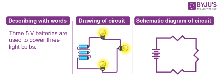
. Three-phase electric power abbreviated 3φ is a common type of alternating current used in electricity generation transmission and distribution. Steps to draw the Phasor Diagram of the RLC Series Circuit. Take current I as the reference as shown in the figure above.
When a segment lights up write down the segment name A-G or DP next to the corresponding pin on your diagram. Manual transfer sub panel switches are a good optionThey are less expensive than automatic transfer switches Starting around 300 and. IDM Members meetings for 2022 will be held from 12h45 to 14h30A zoom link or venue to be sent out before the time.
Electric power transmission is the bulk movement of electrical energy from a generating site such as a power plant to an electrical substationThe interconnected lines which facilitate this movement are known as a transmission networkThis is distinct from the local wiring between high-voltage substations and customers which is typically referred to as electric power. The voltage rise is not given by the turns ratio like in a standard transformer but is proportional to the rate of change of current in the primary circuit. The voltage across the inductor L that is V L is drawn leads the current I by a 90-degree angle.
Automatic transfer switches will sense a power loss start your standby generator and automatically move your load to the generatorThese are awesome but very expensive and require a full-time dedicated standby generator. Due to sluggish behavior lead acid is rated at 02C 5h and 005C 20h. This vi negar battery easily runs these devicesTake the back off of an inexpensive calculator remove the battery extend the two battery wires out the.
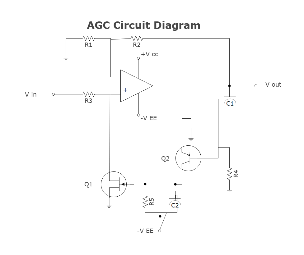
The sense inputs have a rail-to-rail common mode range so the circuit breaker can protect bus voltages from 0V up to 6V. With all the different ways capacitors are labeled figuring out the values of your capacitors can be challenging. 125V Electronic Circuit Breaker Figure 160 The LTC4213 provides protection and automatic circuit breaker action by sensing drain-to-source voltage drop across the N-MOSFET.
In this tutorial Ill show you how to build three different capacitance meters using an Arduino and a couple resistors. The length of the line would then be scaled to P 1 assuming the. Typical discharge curves of lead acid as a function of C-rate.
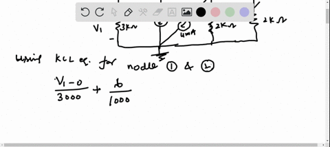
It is the basic storage element in sequential logicFlip-flops and latches are fundamental building blocks of digital. In R₁ ww V₁ R₂ www C₂ C1 V₂ Figure 4 V. A point with a reflection coefficient magnitude 063 and angle 60 represented in polar form as is shown as point P 1 on the Smith chart.
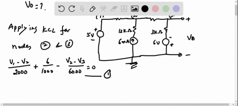
For the circuit shown in Figure 4 use Kirchhoffs Current Law to write a nodal equation for the voltage V₁ in terms of Vin and Vout- V. Experience a great time with our luxury VIP escort girls. My 2006 Freelander factory fitted electrics are 25mm sq and work fine with our 2011 Sterling Celebration 550.
An electron transfer mechanism that involves a light-triggered geometric conversion between metal and oxygen redox chemistry shows superior performance compared with approaches that use either. This apparatus makes circuit building easier by keeping the breadboard and the RedBoard Qwiic microcontroller connected together without the worry of disconnecting or damaging your circuit. These are shown in the circuit diagram and input and output waveforms of an inverting comparator with a 0V reference voltage.
One of the most flexible of SVGs primitive objects is the path. Three-phase electrical power was. Connecting Single Digit Displays to the Arduino.
One of the simplest ways to make a battery powered High Voltage power supply is to use a common car ignition coil. Figure 1 illustrates the capacity drop of 11 Li-polymer batteries that have been cycled at a Cadex laboratory. The 1500mAh pouch cells for mobile phones were first charged at a current of 1500mA 1C to 420Vcell and then allowed to saturate to 005C 75mA as part of the full charge saturation.
With the common pin connected to the ground wire common cathode or positive wire common anode probe each pin with the other wire. To plot this one may use the circumferential reflection coefficient angle scale to find the graduation and a ruler to draw a line passing through this and the centre of the Smith chart. Before you can build circuits youll want to first assemble the breadboard baseplate.
It is a type of polyphase system employing three wires or four including an optional neutral return wire and is the most common method used by electrical grids worldwide to transfer power. Explain why care is required when changing the DMM setting from resistance to voltage and suggest a procedure to avoid experiencing problems. In the Or circuit shown in Figure 111 one of the relays to which the inputs A B C are connected ensures that the bobbins energy is lit by the output lamp that is the output is logic 1.
The voltage across the capacitor c that is V c is drawn lagging the current I by a 90-degree angle because in capacitive load the current leads the voltage by an angle of. Ignition coils are a type of induction transformer based on the Tesla Coil invented by Nikola Tesla in 1891. After finishing this project youll be able to measure all of your capacitors and.
Figure 22 shows a DMM that can be connected across a power supply to measure its voltage. Body figure and appearance. Now draw a diagram showing the pins on your display.
Zero-Crossing Detector Using UA741 op-amp IC As shown in the waveform for a reference voltage 0V when the input sine wave passes through zero and goes in positive direction the output voltage Vout is driven into. LCD calculators draw very little current. VIP Model 16.
Uses a series of lines splines either cubic or quadratic and elliptical arcs to define arbitrarily complex curves that. While lead- and nickel-based batteries can be discharged at a high rate the protection circuit prevents the Li-ion Energy Cell from discharging. The standard 13 core cable for a 13 pin plug on a caravan uses 25mm sq for the charging and fridge circuits earth returns and 15mm sq for the road lights.
Smaller batteries are rated at a 1C discharge rate. In electronics a flip-flop or latch is a circuit that has two stable states and can be used to store state information a bistable multivibratorThe circuit can be made to change state by signals applied to one or more control inputs and will have one or two outputs. Call us 24X7 9831443300 for No1 and cheap Escort Service in Aerocity and have a collection of hot sexy high profile class independent young teen escorts and housewife with whatsapp no.
Especially if you dont have a digital multi-meter to test them. In the Nand circuit shown in Figure 110 if the coil voltage of any relay is disconnected current will flow through the normally closed contact. Assume that having measured voltage you now wish to measure the power supply resistance.
Circuit Diagram And Its Components Explanation With Circuit Symbols
Solved Draw A Circuit Diagram For The Circuit Of Figure P23 1
How To Create Circuit Diagram

Toward Nanopore Electrospray Mass Spectrometry Nanopore Effects In The Analysis Of Bacteria Acs Central Science

Simple Electrical Circuits For Diploma Engineering Students
Draw The Circuit Diagram To Represent The Circuit Shown In Fig 14 21 Sarthaks Econnect Largest Online Education Community
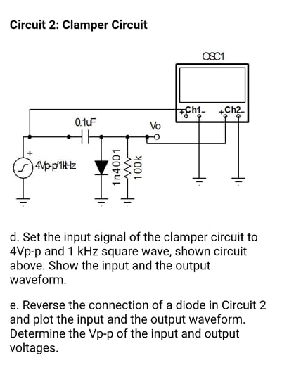
Answered Circuit 2 Clamper Circuit Osc1 Ch2 Bartleby
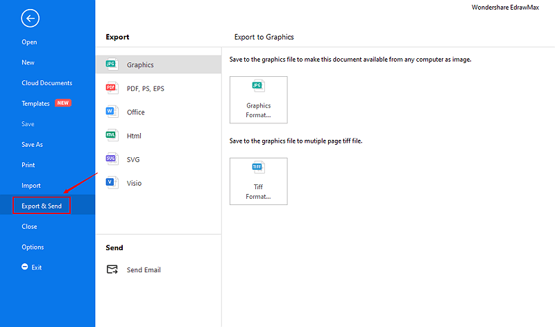
How To Draw A Circuit Diagram Edraw

How To Create Circuit Diagram

Hitachi Zx470 5b 470lc 5b 470h 5b 470lch 5b 470r 5b 520lch 5b Excavator Electrical Circuit Diagram By Heydownloads Issuu

Android Operating System Wikipedia

Electronic Devices And Amplifier Circuits With Matlab Applications Steven T Karris Notas De Estudo Engenharia Eletrica Docsity

Electrically Conductive Metal Organic Frameworks Chemical Reviews
Solved Please See Attachments For Details Course Hero
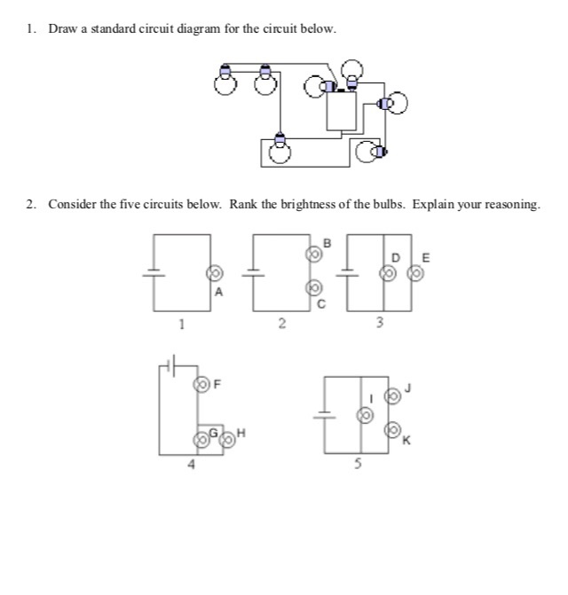
Solved 1 Draw A Standard Circuit Diagram For The Circuit Chegg Com

Q2 Draw The Circuit Diagram To Represent The Circuit Shown In The Figure
Solved Draw A Circuit Diagram For The Circuit Of Figure P23 1